Jet Engine Component; Torque Meter, Helical Gear Train type


$5.70 Jet Engine Component; Torque Meter, Helical Gear Train type
Published 2019-06-28T08:55:10+00:00
Engines that use rotational output (Turboprop, Turboshaft) incorporate the torque meter system that uses the opposite torque of the engine output.
There are various methods, but in engines in which the engine and reduction gear are integrated, the one utilizing engine oil is often used.
By replacing the anti-torque with axial movement and adjusting the opening of the valve, it balances the pressure in the piston and cylinder with the anti-torque axial force.
Then, this pressure is displayed on the cockpit panel as the torque meter and used to control the engine.
As the method to generate that axial movement;
【Ⅰ】Planetary gear used spur gears (carrier shaft is as the output shaft) has been made.
Add the helical spline around the ring gear and use the axial force generated in the ring gear.
This method provides a relatively large piston area, so engine oil pressure can be used.
https://www.myminifactory.com/object/3d-print-jet-engine-component-torque-meter-planetary-gear-type-95672
【Ⅱ】Planetary gear used helical gears (ring gear is as the output shaft)
Use axial force generated on carrier gear (s)
This method requires a higher pressure pump for torque meter because each piston area is narrow.
【Ⅲ】Reduction gear with the helical gear train (mainly for turboshaft engines)
Use axial force generated on the intermediate gear. (This is it.)
【Ⅳ】Others
Some engine use the difference in torsion between two or one shaft (hydraulic or electrical).
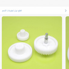
This model reproduces the【Ⅲ】method as the cutaway model.
The components of this model are:
① Helical Gear Train (Drive Gear, Inter-Gear, Output Gear)
② Inter-Gear contained Torque Meter Mechanism
③ Torque Meter Shaft with Piston (Fixed)
④ Toque Meter Cylinder with Control Port (Moving)
⑤ Bearings: 2 Roller Bearings (for Radial Force), 1 Ball Bearing (for Axial Force)
All bearings are printed except Balls.
⑥ Gearbox Housings (to support front and rear of Torque Meter Shaft)
⑦ Oil passage (engine oil, torque meter oil, bleed)
But O-rings are omitted at this model.
⑧ Output Gear is cut because of reduce print size and fixed.
By reproducing the anti-torque with turning the Drive Gear, you can see the movement of the Inter Gear and Cylinder.
Some of the design changes have been made because the oil pressure to move the cylinder backwards cannot be used.
B. Assembly Manual (PDF format, total 15 pages)
The detail assembly manual including "Parts-List", "After printing treatment" and "Assembly procedure" are prepared based on "Standard Skill (Filing, Drilling, Tapping, gluing and tightening)".
C. Purchase Parts
1. All Bearings are printed. (except 8mm Balls).
2. Screws
M1.4x6L, M2x10L, M4x20L
D. STL file
Total STL files are 28 items including the stand and tools.
“ws” of last 2 digits of file name means “With Support” special designed.
E. Total Net Print Time: Approx. 49HR
- (Estimated as case of PLA, 0.4mm Nozzle, 0.2mm Layer Height, 40% infill and No raft and support)
Note: When at actual print, each parameter may be adjusted by your experience.
F. Printing settings
Raft, Support, Layer Height, Infill: Depending on your experience.
My models were printed by "idbox" using with 0.4 nozzle, 1.75 PLA.
I do hope your success!!
See above
| Date published | 28/06/2019 |
| Price | $5.70 |

Mersi