MyRCCar 1/10 GT500 1967 American Muscle On-Road RC car body


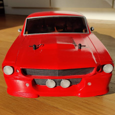
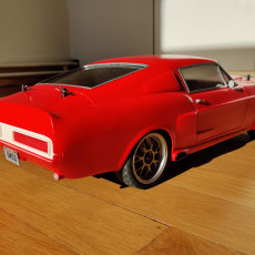

MyRCCar 1/10 GT500 1967 American Muscle On-Road RC car body
Published 2020-07-31T14:58:45+00:00
Here you have the best model until now published into the MyRCCar ecosystem ;)
Old Price: 29.21
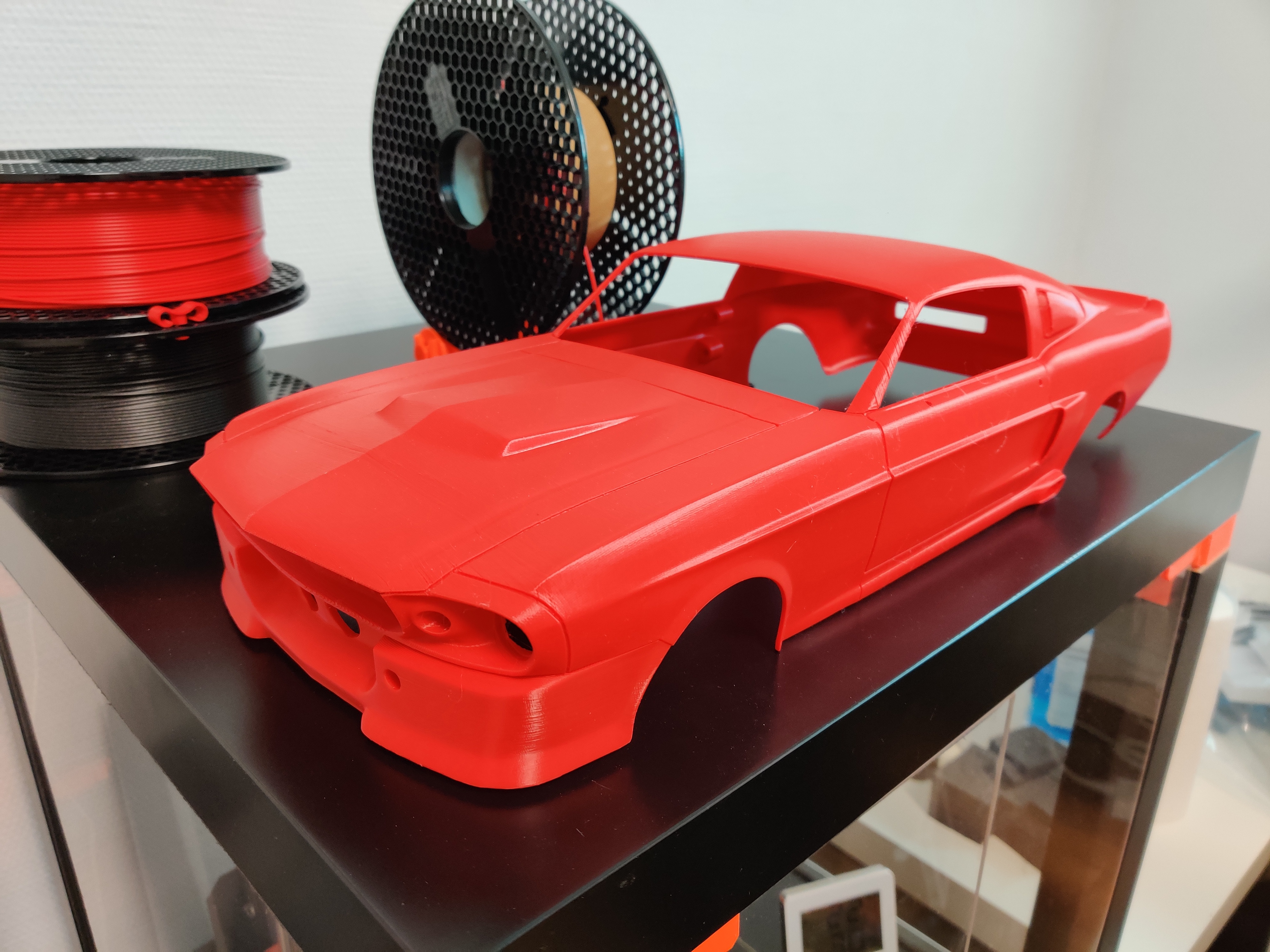
This is a great work from my cousin Rockser3D. He has model completely this nice 1/10 RC car body, always with FDM 3D printing in mind.
If you want to see it in 3D take a look to the 3D scan with the KIDS chassis
MAIN FEATURES:
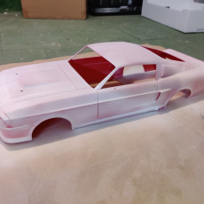
- The model is divided in 3 main parts, some other smaller parts as front bumper or rear trunk and a lot of extra detail parts as lights, mirrors, windows, handlers, fuel cup, radiator and some more.
- It has 8 holes for lights in the front and another 8 in the rear so you can make a good "Light Show" with this one ;)
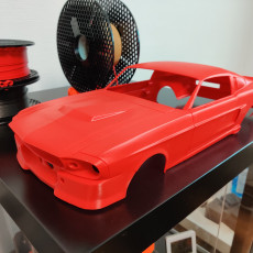
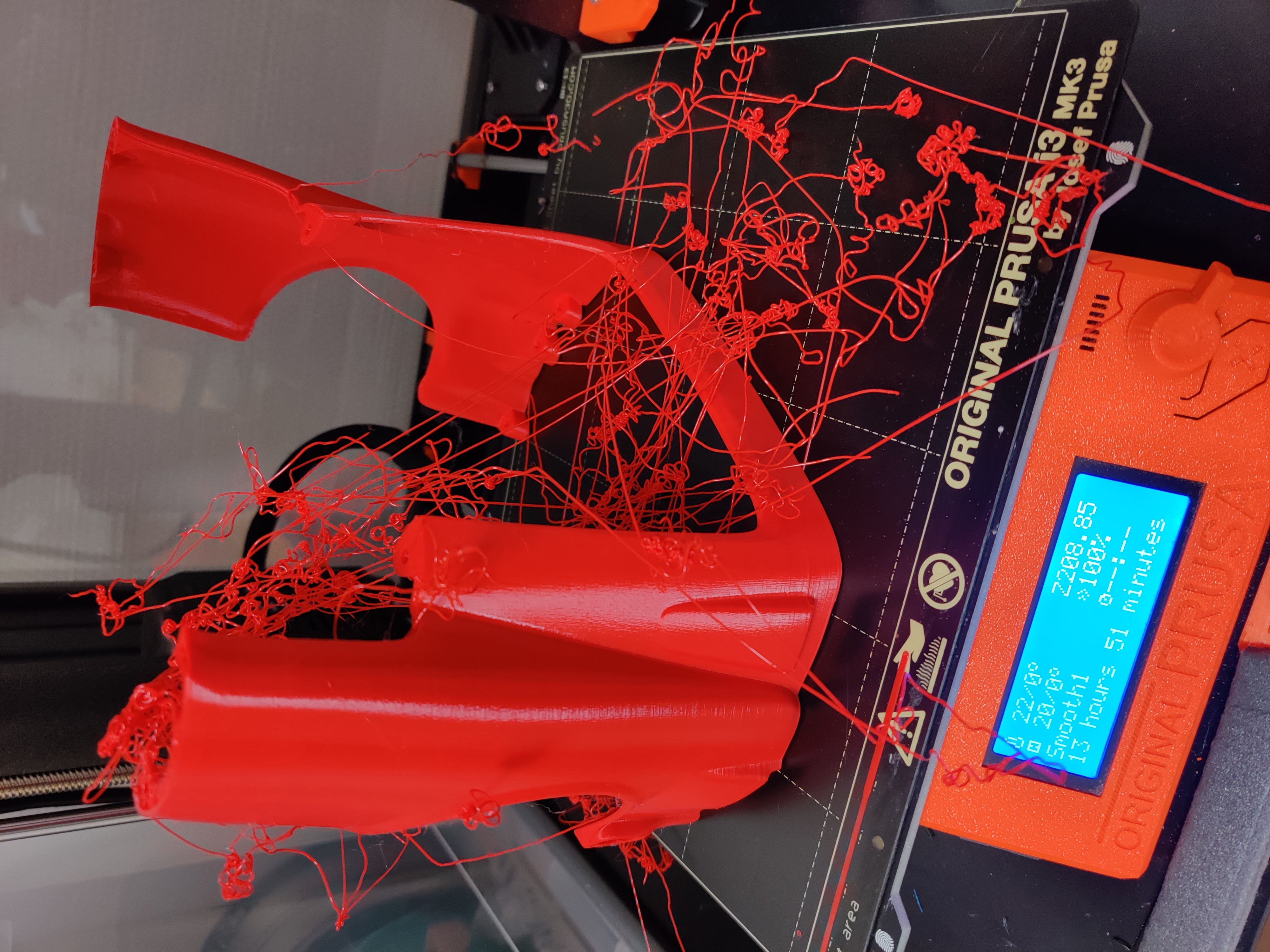
- Printed in PLA it can survive some rollings (it did) but probably it won't be undestructible for some other kind of hits.
- You will need something between 500g and 1000g of plastic to build the body. It has no flexible parts (recommended rearviews in TPU) but you could need transparent PLA to make the windows and light lenses.
- The big parts are screwed between them instead of glued, which makes the assembled body to feel quite rigid!
- You will need very little or no supports for the 3 main big parts and just some smaller supports for some of the detail parts
SPECS:
- Total width (without rearviews): 200mm
- Total length: 490mm
- Wheelbase: 280mm
- Height: ~120mm
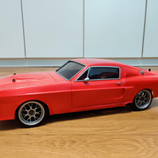
Under the hood there is actually a MyRCCar KIDS On-Road Chassis and I'm using some flexible holders for the body, which make the pack quite resistant to smaller impacts and manipulation.
If you have a 280mm wheelbase chassis with an axle width smaller than 195mm (maybe even little less) you will probably be able to use this body too! You will need to do the holes in the right place for your body holders or glue your magnets. You will also need a "low profile" chassis front part to be able to accommodate the body as low as possible.
I have supplied you with two versions for the windows. In the 1piece version, frame and glass will be just one part. In the other hand, you can find "frames" and "Glass" for each window if you preffer to print them separately.
If you are going to use it with MyRCCar KIDS On-Road, you will need some "Spacers" for the rear body holding system. Those ones are also provided.


PRINTING TIPS:
Main Body Parts:
This body has been designed as a 2mm thickness shell, so to better print it, use 0.48-0.5mm perimeter thickness.
To print the main parts as we did, you will need to rotate them 78º. Rotate cabin and rear part +-78º until the plane surface which separates them is against the bed. You should not need supports for cabin and rear parts.
If you want to keep same layer alignement for the front part, rotate it also 78º until the plane short cut near rearviews is paralell to the bed. Add the needed supports to the part to be able to start building, but avoid high supports, as the higher zones of the part has been modeled to avoid them.
The Bumper can be printed as is, but you will need to rotate the trunk so the rear flat surface is against the bed and add a few supports to hold the surfaces where rear lights are installed.
These parts has some overhangs which can be correctly done in 0.2mm height layers and with 0.48mm perimeter thickness, at last in all visible zones.
Why 0.48-0.5mm perimeter thickness?¿?
The idea for a "perfect shell" is avoiding as much retractions and travels as possible. For that reason, if the shell is 2mm thick, with 0.5mm perimeters you should have just the inner and the outer perimeters in most of your layers, avoiding solid and standard infills which use to produce this kind of retractions and travels.
Seam alignement?¿?
"Optimize" the start and order in which perimeters are done can be the right choice for many things to print, but if you want the best result possible in your main body parts, you will have to choose, if your slicer allows it, the best point to align most of the starts/ends of the perimeters. The start and end of perimeters and their near zones are more susceptible to lead into little errors, like blobs, underextrusion at the start of perimeters after big travels or after many consecutive retractions... So the idea is to hide this points of each layer in a less visible place of the part... So the inner side of the part could be good to us.
A very fine tuned 3d printer won't fail after big travels and many retractions in a row, specially if new, but many others could have these kind of little fails which lead into a worse finish of the part.
So for those of us, choosing a point in the inner side of the part could be good, but if you choose a point of the inner shell where the starts of perimeters will print along the inner shell, better than better. That way, if some underextrusion at the beggining of perimeters occur, it will be in the inner side of our part.
Detail Parts:
For the detail parts, you will need to take out the best of your knowledge about 3D printing, as some parts are quite little and many of them will need supports.
With the exception of the rearviews (TPU better) all of them can be printed in PLA.
You will need to be able to print 0.08, 0.1 or 0.12mm layers to achieve as much quality as possible
You will need to find the best position in which you think it will print better. Think about how it will look with the rest of the parts, but also try to find a position in which adding a few supports most of the part can be printed.
Going beyond the limits:
Very probably you will need to reduce your perimeter thickness to 0.4 OR MORE! to be able to accurately print some of the detail parts. For those of us with 0.4mm nozzles, we are supposed to never use perimeter thickness lower than 0.48mm for a correct extrusion, but for some particular cases, specially small parts without big travels or great overhangs you can go thinner and thinner.
I have printed as low as 0.2 or 0.25mm perimeters with a 0.4mm nozzle... but... how can that be done?¿? If you make very thin layers, lets say 0.1mm but use very thick perimeters, then your WOH value will be too high, leading into not very good results while printing some characteristics... I have printed little parts with 0.12x0.24 perimeters, 0.12x0.36, 0.1x0.33, 0.1x0.25... The limit, as they are little "fast" low weight parts, is your patience ;)
If you are going to go beyond limits, remember to have a very good first layer, probably thicker and higher than the rest, and your extruder primed before the first layer starts... I mean maybe free extruding 20mm filament at the begining and printing some skirt lines before first layer of the part is printed
Windows, the final challenge!
Ideally, you will print the window frames in one material and the cristals in some transparent PLA or PETG... But specially the frames can be really tricky to print due to their extra thin profile.
If you don't mind to paint the frame black, you can print the "1piece" version of the windows which can be a little easier. Try to find the perimeter thickness that fills the profile shape as much as possible, and a thin height so the WOH doesn't get too high. Give it a try, and if you can't get rid of it I will try to supply you an easier to print version, but it won't be such as stylized as this one.
Sinking a little:
Sometimes, for some parts, in some positions, you can "sink" the part in the bed a very little distance to have a good first layer. At least, I use to "sink" some parts, in a place that is not visible and doesn't affect functionallity. So sometimes sinking it 0.05, 0.1, 0.15, 0.2 mm can give you inner and outer perimeter in the first layer, while if you don't do it, you practically start building your part all over supports.
Inter-Layer Adhesion:
For some of the parts, specially the big ones, you want a good inter-layer adhesion so remember to print in the high range of PLA, something between 210 and 220 if you can, as your layers will stick to the previous one much stronger. This could lead into more stringing or into some underextrusion after big travel and some oozing, but if you use fast travel speed these effects will be reduced.
GENERAL PRINTING PROFILE:
For the big parts (fast profile):
- 0.2mm layer height
- 2 perimeters, 5 tops and 5 bottom
- 0.4 to 0.48 perimeter thickness, depends of the part
- 15-25% infill normally, 1000tops/bottoms if 100% solid weight differs a little
- 70mm/s general speed, 50% for outer perims, 80% for solid infill and supports
- 240mm/s travels, quite fast, if your printer allows them
- 400mm/s2 accel for printing moves
- 2000mm/s2 accel for travels
- 220ºC for PLA or less if reduced general speed, 45ºC Bed, printed over crystal
- 50% layer fan (needed in overhang zones specially, 100% for bridges)
For the detail parts:
- 0.1mm layer height
- 3 perimeters, 10 tops and 9 bottom
- 0.25 to 0.4 perimeter thickness, depends of the part
- Solid infill, 1000tops/bottoms
- 40mm/s general speed, 50% for outer perims, 80% for solid infill and supports
- 200mm/s travels, quite fast, if your printer allows them
- 400mm/s2 accel for printing moves
- 1200mm/s2 accel for travels
- 210ºC for PLA or less if reduced general speed, 45ºC Bed, printed over crystal
- 60% layer fan (up to 100% for layers faster than 5s)
Anyway, I use to review and adapt these parameters for each part I print. One profile to rule them all would be good, but I have not found it already
| Date de publication | 31/07/2020 |
| Durée d’impression | 20 - 60 minutes |
| Quantité de filament | >500g |
| Dimensions | minimum 200x200x220 printing volume |
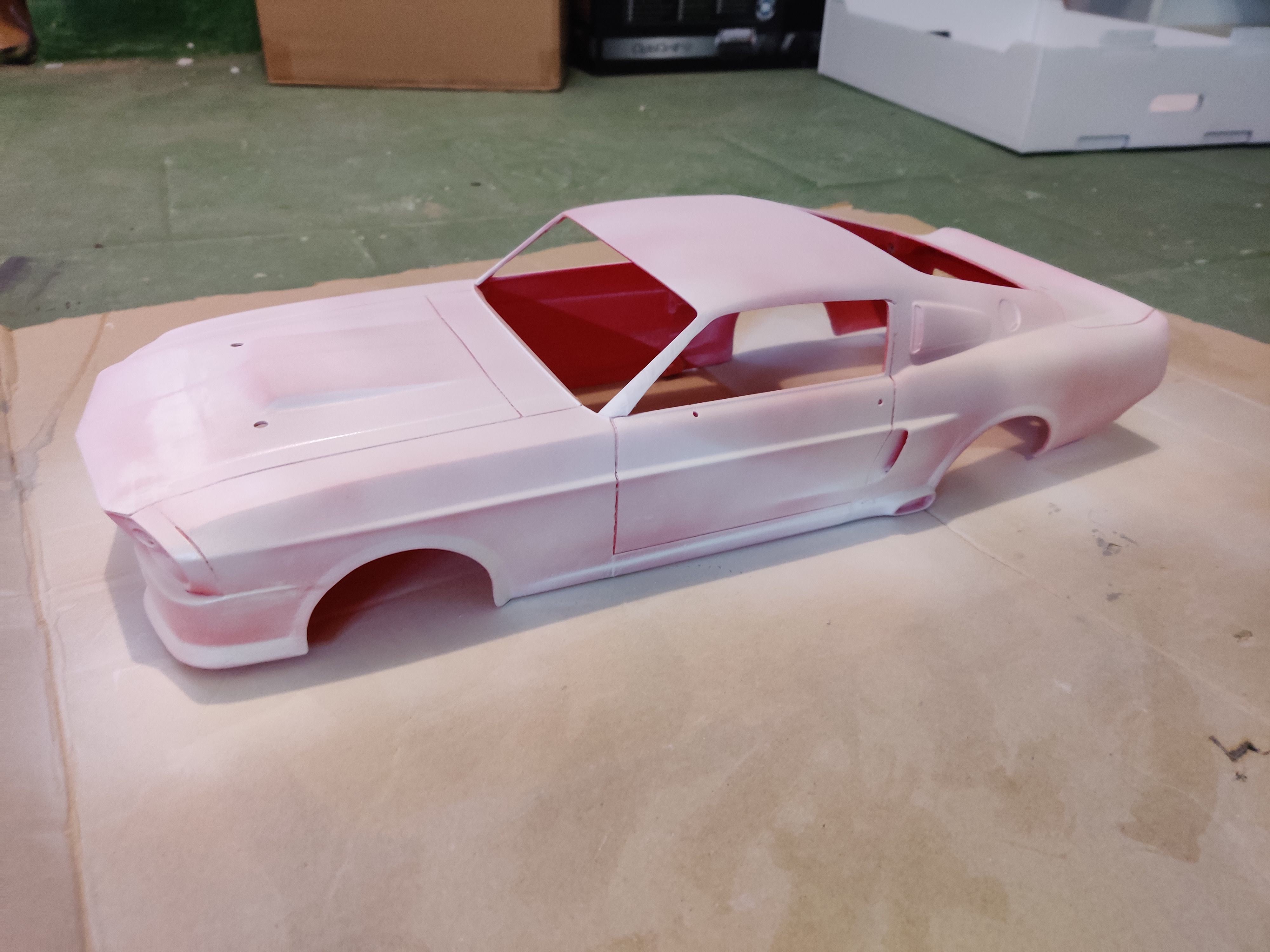
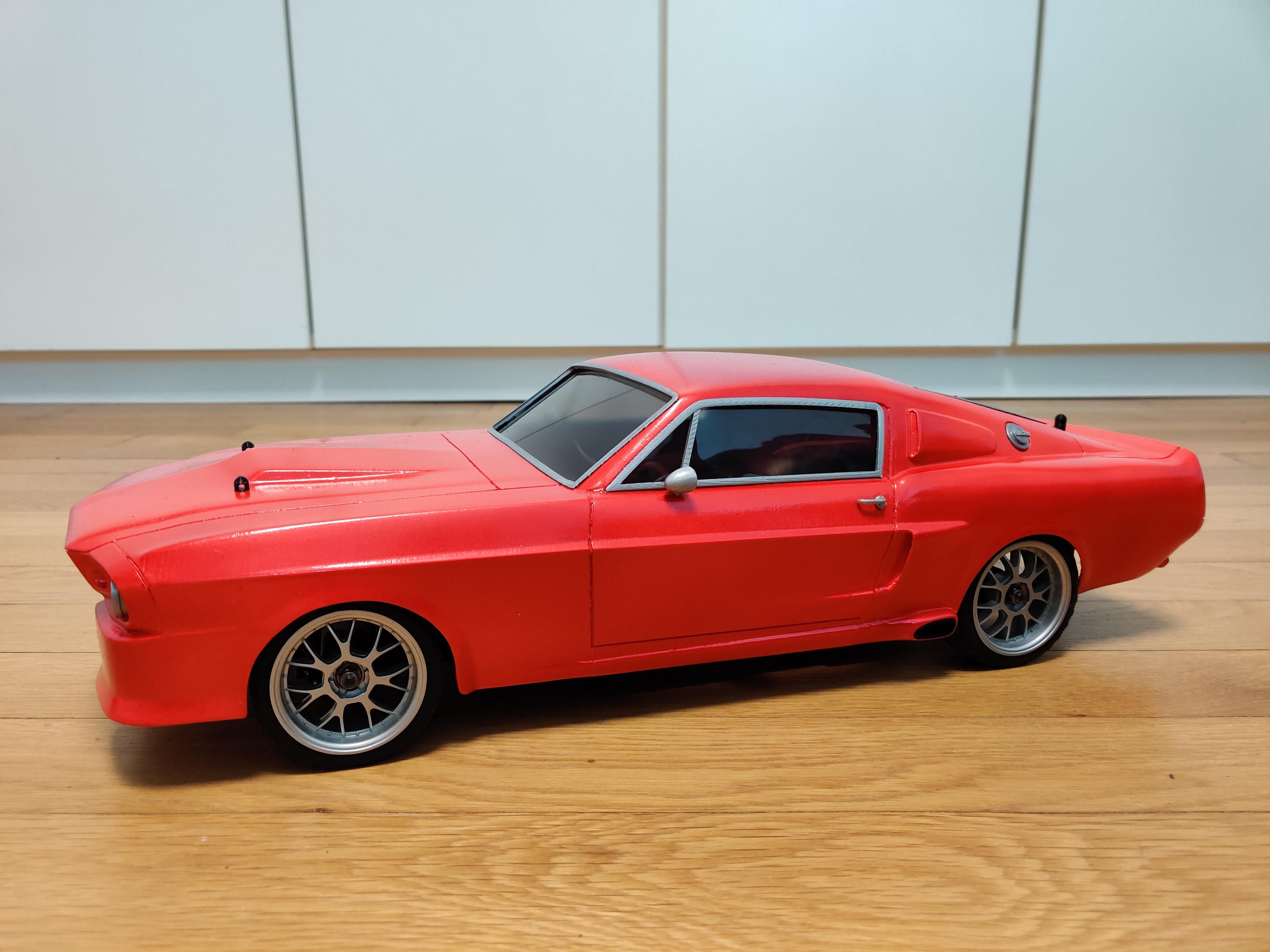
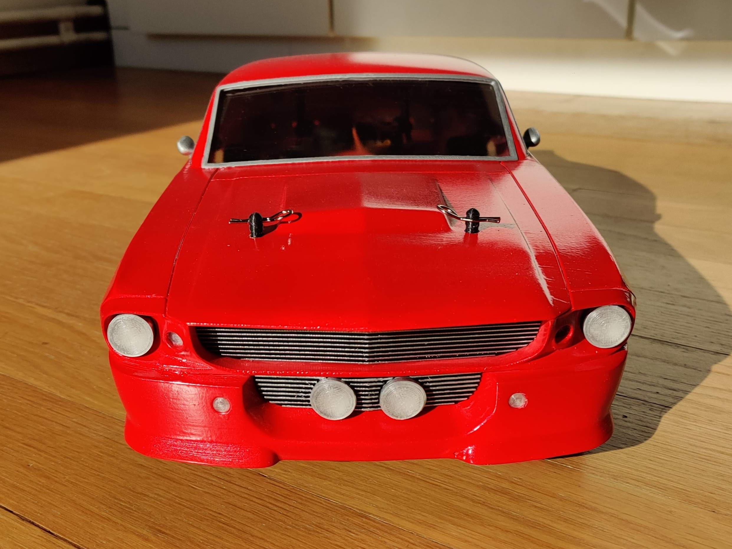
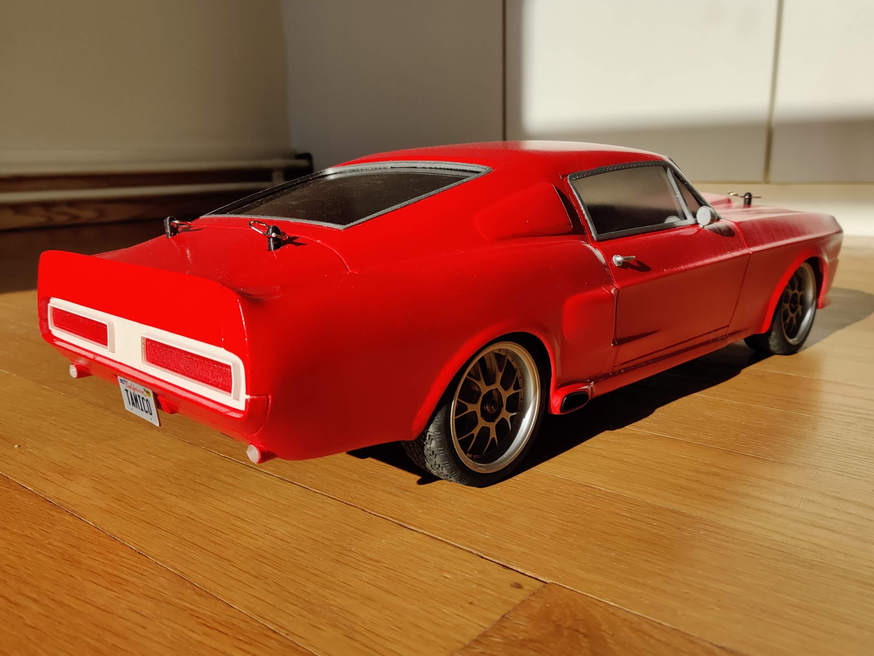
Printed using PLA, sanded, filled, primer, painted with Tamiya TS-39 Mica Red. Windows using Lexan (Polycarbonate) 0.5 mm sheet painted with Tamiya PS-31 Smoke Front Lights printed with transparent PC Rear lights transparent red PETG